Chevrolet Captiva Service & Repair Manual: Parking Brake Cable R&R
Front
Removal
| 1. |
Disable the parking brake cable adjuster. |
| 2. |
Turn the ignition to the OFF position. |
| 3. |
Raise and support the vehicle. |
| 4. |
Disconnect the parking brake cable
nut (1) from the electronic parking brake control module spindle
by rotating the nut counterclockwise, Fig. 1. |
| 5. |
Disconnect the parking brake cable
and position the cable aside. |
| 6. |
If unable to disconnect the parking
brake cable from the electronic parking brake control module, it
may be necessary to manually release the parking brake cable tension,
noting following: |
| |
a. |
Remove the electronic parking brake
control module front cover. |
| |
b. |
Perform the manual parking brake cable
tension release procedure. |
| 7. |
Remove the parking brake cable forward
bracket bolt (1), Fig. 2. |
| 8. |
Lower the rear suspension support approximately
6-10 inch to access the parking brake cable fasteners. |
| 9. |
Remove the parking brake cable lower
support bracket bolt (1), Fig. 3. |
| 10. |
Remove the parking brake cable upper
support bracket bolt (1), Fig. 4. |
| 11. |
Disconnect the parking brake cable
from the right rear parking brake cable connector (1), Fig.
5. |
| 12. |
Using the CH-37043 Parking Brake Cable
Release Tool, compress the locking tabs on the left rear parking
brake cable conduit (1) and remove the parking brake cable from
the support bracket, Fig. 6. |
| 13. |
Disconnect the left rear parking brake
cable from the parking brake cable equalizer. |
| 14. |
Disconnect the left parking brake cable
eyelet (1) from the parking brake actuator, Fig. 7. |
| 15. |
Using the CH-37043 Parking Brake Cable
Release Tool, remove the parking brake cable (2) from the parking
brake cable bracket, Fig. 7. |
| 16. |
Remove the parking brake cable from
the rear suspension support. |
|
Installation
| Ensure the park brake cable fitting
is engaged in the actuator in the spindle. |
| When installing the parking brake
intermediate cable nut to the electronic park brake module spindle, hold
the spindle housing securely to avoid distorting the housing. |
| 1. |
Install the parking brake cable assembly
to the vehicle. |
| 2. |
Connect the left parking brake cable
eyelet to the parking brake actuator. |
| 3. |
Install the left parking brake cable
to the parking brake cable bracket. |
| 4. |
Ensure the locking tabs on the cable
conduit are securely engaged to the cable bracket. |
| 5. |
Connect the left rear parking brake
cable to the parking brake cable equalizer. |
| 6. |
Install the parking brake cable to
the support bracket. |
| 7. |
Ensure the locking tabs on the left
rear parking brake cable conduit are securely engaged to the support
bracket. |
| 8. |
Connect the parking brake cable to
the right rear parking brake cable connector. |
| 9. |
Install the parking brake cable upper
support bracket bolt and torque to 18 ft. lbs. |
| 10. |
Install the parking brake cable lower
support bracket bolt and torque to 18 ft. lbs. |
| 11. |
Install the rear suspension support. |
| 12. |
Install the parking brake cable forward
bracket bolt and torque to 18 ft. lbs. |
| 13. |
Inspect the O-ring seals on the electronic
parking brake control module spindle and the parking brake cable
for damage and correct positioning and replace, if necessary. |
| 14. |
If removed, install the electronic
parking brake control module front cover. |
| 15. |
Install the parking brake cable fitting
to the spindle. |
| 16. |
Connect the parking brake cable nut
to the electronic parking brake control module spindle by rotating
the nut clockwise and torque to 53 inch lbs. |
| 17. |
Enable the parking brake cable adjuster. |
|
Rear
| Warning: Avoid taking the following
actions when you service wheel brake parts: Do not grind brake linings,
do not sand brake linings and do not clean wheel brake parts with a dry
brush or with compressed air. |
| Warning: Some models or aftermarket
brake parts may contain asbestos fibers which can become airborne in dust.
Breathing dust with asbestos fibers may cause serious bodily harm. Use a
water-dampened cloth in order to remove any dust on brake parts. Equipment
is available commercially in order to perform this washing function. These
wet methods prevent fibers from becoming airborne. |
Lefthand Side
Removal
| 1. |
Disable the parking brake cable adjuster. |
| 2. |
Turn the ignition to the OFF position. |
| 3. |
Raise and support the vehicle. |
| 4. |
Remove the tire and wheel assembly. |
| 5. |
Disconnect the parking brake intermediate
cable nut (1) from the electronic parking brake control module spindle
by rotating the nut counterclockwise, Fig. 8. |
| 6. |
Disconnect the parking brake intermediate
cable and position the cable aside. |
| 7. |
Remove the intermediate parking brake
cable forward bracket bolt (1), Fig. 9. |
| 8. |
Lower the rear suspension support approximately
6-10 inch to access the parking brake cable fasteners. |
| 9. |
Remove the intermediate parking brake
cable lower support bracket bolt (1), Fig. 10. |
| 10. |
Remove the intermediate parking brake
cable upper support bracket bolt (1), Fig. 11. |
| 11. |
Disconnect the intermediate parking
brake cable from the right rear parking brake cable connector (1),
Fig. 12. |
| 12. |
Using the CH-37043 Parking Brake Cable
Release Tool, compress the locking tabs on the left rear parking
brake cable conduit (1) and remove the parking brake cable from
the support bracket, Fig. 13. |
| 13. |
Disconnect the left rear parking brake
cable from the parking brake cable equalizer. |
| 14. |
Disconnect the left parking brake cable
eyelet (1) from the parking brake actuator, Fig. 14. |
| 15. |
Using the CH-37043 Parking Brake Cable
Release Tool, remove the parking brake cable (2) from the parking
brake cable bracket, Fig. 14. |
| 16. |
Remove the intermediate parking brake
cable from the rear suspension support. |
| 17. |
Separate the intermediate and rear
left parking brake cables. |
|
Installation
| Ensure the park brake intermediate
cable fitting is engaged in the actuator in the spindle. |
| When installing the parking brake
intermediate cable nut to the electronic park brake module spindle, hold
the spindle housing securely to avoid distorting the housing. |
| 1. |
Connect the intermediate and rear left
parking brake cables. |
| 2. |
Connect the left parking brake cable
eyelet to the parking brake actuator. |
| 3. |
Install the left parking brake cable
to the parking brake cable bracket. |
| 4. |
Ensure the locking tabs on the cable
conduit are securely engaged to the cable bracket. |
| 5. |
Connect the left rear parking brake
cable to the parking brake cable equalizer. |
| 6. |
Install the parking brake cable to
the support bracket. |
| 7. |
Ensure the locking tabs on the left
rear parking brake cable conduit are securely engaged to the support
bracket. |
| 8. |
Connect the intermediate parking brake
cable to the right rear parking brake cable connector. |
| 9. |
Install the intermediate parking brake
cable upper support bracket bolt and torque to 18 ft. lbs. |
| 10. |
Install the intermediate parking brake
cable lower support bracket bolt and torque to 18 ft. lbs. |
| 11. |
Install the intermediate parking brake
cable forward bracket bolt and torque to 18 ft. lbs. |
| 12. |
Install the rear suspension support. |
| 13. |
Inspect the O-ring seals on the electronic
parking brake control module spindle and the parking brake intermediate
cable for damage and correct positioning and replace, if necessary. |
| 14. |
Install the parking brake intermediate
cable fitting to the spindle. |
| 15. |
Connect the parking brake intermediate
cable nut to the electronic parking brake control module spindle
by rotating the nut clockwise and torque to 53 inch lbs. |
| 16. |
Install the tire and wheel assembly. |
| 17. |
Enable the parking brake cable adjuster. |
|
Righthand Side
Removal
| 1. |
Disable the parking brake cable adjuster. |
| 2. |
Turn the ignition to the OFF position. |
| 3. |
Raise and support the vehicle. |
| 4. |
Remove the tire and wheel assembly. |
| 5. |
Disconnect the right parking brake
cable eyelet (1) from the parking brake actuator, Fig.
15. |
| 6. |
Using the CH-37043 Parking Brake Cable
Release Tool, remove the parking brake cable (2) from the parking
brake cable bracket, Fig. 15. |
| 7. |
Lower the rear suspension support approximately
6-10 inch to access the parking brake cable fasteners. |
| 8. |
Remove the right parking brake cable
lower support bracket bolt (1), Fig. 16. |
| 9. |
Remove the right parking brake cable
upper support bracket bolt (1), Fig. 17. |
| 10. |
Disconnect the intermediate parking
brake cable from the right rear parking brake cable connector (1),
Fig. 18. |
| 11. |
Using the CH-37043 Parking Brake Cable
Release Tool, compress the locking tabs on the right rear parking
brake cable conduit (1) and remove the parking brake cable from
the support bracket, Fig. 19. |
|
Installation
| 1. |
Install the right parking brake cable
to the support bracket. |
| 2. |
Ensure the locking tabs on the right
rear parking brake cable conduit are securely engaged to the support
bracket. |
| 3. |
Connect the intermediate parking brake
cable to the right rear parking brake cable connector. |
| 4. |
Install the right parking brake cable
upper support bracket bolt and torque to 18 ft. lbs. |
| 5. |
Install the right parking brake cable
lower support bracket bolt and torque to 18 ft. lbs. |
| 6. |
Install the rear suspension support. |
| 7. |
Connect the right parking brake cable
eyelet to the parking brake actuator. |
| 8. |
Install the parking brake cable to
the parking brake cable bracket. |
| 9. |
Install the tire and wheel assembly. |
| 10. |
Enable the parking brake cable adjuster. |
|
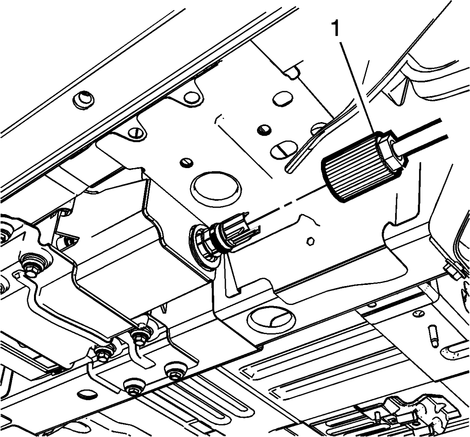
Fig.
1

Fig.
2

Fig.
3

Fig.
4

Fig.
5

Fig.
6
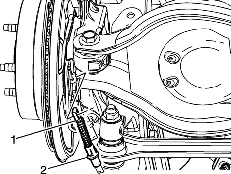
Fig.
7

Fig.
8
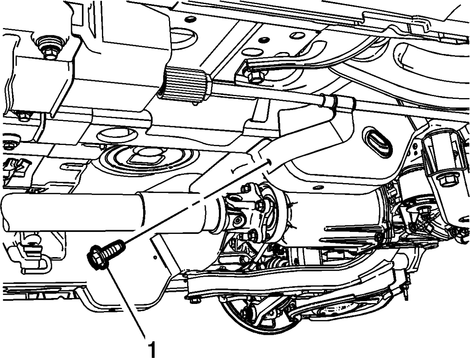
Fig.
9
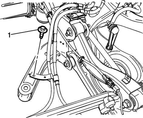
Fig.
10
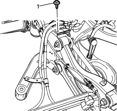
Fig.
11
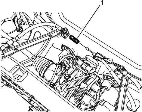
Fig.
12
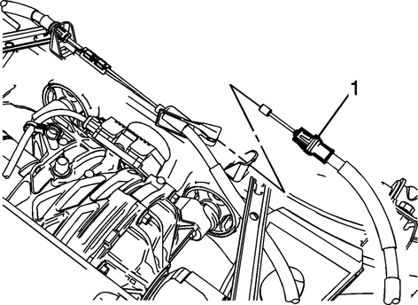
Fig.
13

Fig.
14
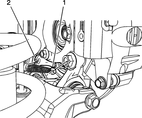
Fig.
15
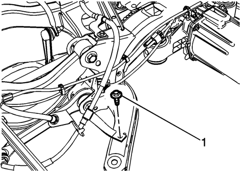
Fig.
16
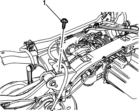
Fig.
17

Fig.
18
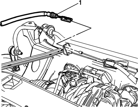
Fig.
19
Servicing the parking brake cable in a first-generation Chevrolet Captiva (C100/C140) involves several steps to ensure proper functionality and safety. Begin by locating the parking brake cable underneath the vehicle. It is usually connected to the rear brake calipers or drums and runs along the underside of the vehicle to the parking brake lever or pedal inside the cabin.
To adjust the parking brake cable, first, ensure the vehicle is safely lifted and supported on jack stands. Locate the adjustment nut or bolt on the parking brake cable near the rear brakes. This nut or bolt is used to adjust the tension in the cable, which in turn affects the parking brake's effectiveness.
Loosen the adjustment nut or bolt slightly to allow for adjustment of the parking brake cable tension. Pull the parking brake lever or pedal inside the cabin to its fully engaged position, and then tighten the adjustment nut or bolt until the parking brake engages securely. Release the lever or pedal and ensure it returns to its resting position without excessive slack in the cable.
Perform a few test applications of the parking brake to ensure it holds the vehicle securely in place without any dragging or excessive noise from the rear brakes. If necessary, fine-tune the adjustment by repeating the process until the parking brake functions smoothly and effectively. Regular maintenance and adjustment of the parking brake cable are essential to ensure the safety and reliability of your Chevrolet Captiva's parking brake system.
Procedure
If the rear wheels rotate during
the following test, repeat the adjustment procedure completely.
1.
Disable the parking brake cable adjuster.
...
Actuator
1.
Raise and support the vehicle.
2.
Remove the tire and wheel.
3.
Remove the park brake shoes.
...
 Parking Brake Cable Adjust
 Parking Brake Motor R&I