Chevrolet Captiva Service & Repair Manual: Component Service
Air Bag Clockspring R&R
| 1. |
Ensure front wheels are in straight
ahead position. |
| 2. |
Remove driver air bag module as outlined
under "Driver Air Bag Module, Replace." |
| 3. |
On models equipped with speed control,
disconnect switch and harness from steering wheel. |
| 4. |
On all models, remove steering
wheel using puller tool No. J-1859-A and legs tool No. J-42578,
or equivalents. |
| 5. |
Remove steering column upper and lower
covers mounting screws. |
| 6. |
Remove ignition switch bezel and column
lower cover. |
| 7. |
Remove clockspring rosebud type fastener
from bracket below steering column. |
| 8. |
Disconnect horn and cruise control
electrical connector under steering column. |
| 9. |
Guide wiring harness from behind lever
control switch and remove clockspring. |
| 10. |
Reverse procedure to install, noting
the following: |
| |
a. |
New clockspring connector is equipped
with yellow tab that is removed after steering wheel is installed.
This tab passes through steering wheel. |
| |
b. |
Ensure clockspring is properly centered
as outlined under "Clockspring, Centering." |
| |
c. |
Ensure electrical connectors and wiring
are properly routed to avoid pinching. |
|
Air Bag Clockspring Centering
| Identify clockspring type as outlined
in chart. |
|
Make & Model |
Year |
Clock Spring Type |
|
BUICK |
|
Enclave |
2012-16 |
Type 2 |
|
Encore |
2013-16 |
Type 3 |
|
CADILLAC |
|
Escalade |
2012-16 |
Type 4 |
|
SRX |
2012-16 |
Type 1 |
|
CHEVROLET |
|
Avalanche |
2012-13 |
Type 4 |
|
Captiva Sport |
2013-14 |
Type 6 |
|
City Express |
2015-16 |
Type 5 |
|
Colorado |
2012 |
Type 2 |
|
2015-16 |
Type 1 |
|
Equinox |
2012-16 |
Type 1 |
|
Express |
2012-16 |
Type 4 |
|
Silverado |
2012-16 |
Type 4 |
|
Suburban |
2012-16 |
Type 4 |
|
Tahoe |
2012-16 |
Type 4 |
|
Traverse |
2012-16 |
Type 2 |
|
Trax |
2013-16 |
Type 3 |
|
GMC |
|
Acadia |
2012-16 |
Type 2 |
|
Canyon |
2012 |
Type 2 |
|
2015-16 |
Type 1 |
|
Savana |
2012-16 |
Type 4 |
|
Sierra |
2012-16 |
Type 4 |
|
Terrain |
2012-16 |
Type 1 |
|
Yukon |
2012-16 |
Type 4 |
|
Yukon XL |
2012-16 |
Type 4 |
|
|
|
|
|
|
|
Type 1
| A new clockspring assembly will
be centered. |
| Improper alignment of SIR coil
assembly may damage unit, causing an inflatable restraint fault. |
| 1. |
Ensure front wheels are straight ahead
position. |
| 2. |
Ensure centering mark of steering shaft
is in 6 o'clock position, Fig. 1. |
| 3. |
Turn lobe of coil clockwise until coil
ribbon stops. Do not force. |
| 4. |
Turn lobe of coil counterclockwise
approximately three turns to neutral position. |
| 5. |
Properly align coil until centering
window turns yellow. Fig. 2. This indicates
center position of coil. |
|
Type 2
| A new clockspring assembly will
be centered. |
| Improper alignment of SIR coil
assembly may damage unit, causing an inflatable restraint fault. |
| If double wire harness strap is
installed onto wire harness assembly and column, reuse holder for wire straps
during installation. Remove wire harness strap(s) where required. |
| 1. |
Ensure front wheels are straight ahead
position. |
| 2. |
Ensure centering mark of steering shaft
is in 12 o'clock position, Fig. 3. |
| 3. |
Ensure ignition switch is in Lock position. |
| 4. |
Hold components with bottom facing
upward. |
| 5. |
While holding clockspring, depress
spring lock to rotate hub six revolutions in direction of arrow. |
| 6. |
Rotate coil hub in opposite direction
approximately 21/2 turns. |
| 7. |
Release spring lock between locking
tabs. |
| 8. |
If front of clockspring has a centering
window and back side includes a spring service lock, Fig.
4, proceed as follows: |
| |
a. |
Hold clockspring with face up. |
| |
b. |
While depressing spring service lock,
rotate coil hub clockwise until coil ribbon stops. |
| |
c. |
Slowly rotate coil hub counterclockwise
until centering window appears yellow and both arrows align. |
| |
d. |
Release spring service lock between
locking tabs. |
| |
e. |
Clockspring is now properly centered. |
| |
f. |
Align clockspring with horn tower and
slide it onto steering shaft. |
| 9. |
If front of clockspring has a centering
window and back side does not include a spring service lock,
Fig. 5, proceed as follows: |
| |
a. |
Hold clockspring with face up. |
| |
b. |
Rotate coil hub clockwise until coil
ribbon stops. |
| |
c. |
Slowly rotate coil hub counterclockwise
until centering window appears yellow and both arrows align. |
| |
d. |
Clockspring is now properly centered. |
| |
e. |
Hold clockspring in centered position,
align it with horn tower and slide it onto steering shaft. |
| 10. |
If front side of clockspring does not
have a centering window, but rear side includes a spring service
lock, Fig. 6, proceed as follows: |
| |
a. |
Hold clockspring with rear side up. |
| |
b. |
While depressing spring service lock,
rotate coil hub in direction of arrow until coil ribbon stops. |
| |
c. |
Keeping service lock depressed, rotate
coil hub counterclockwise 21/2 turns. |
| |
d. |
Release spring service lock between
locking tabs. |
| |
e. |
Clockspring is now properly centered. |
| |
f. |
Align clockspring with horn tower and
slide it onto steering shaft. |
| 11. |
If front side of clockspring has no
centering window and back side has no spring service lock, Fig.
7 proceed as follows: |
| |
a. |
Hold clockspring with rear side up. |
| |
b. |
While depressing spring service lock,
rotate coil hub in direction of arrow until coil ribbon stops. |
| |
c. |
Keeping service lock depressed, rotate
coil hub counterclockwise 21/2 turns. |
| |
d. |
Clockspring is now properly centered. |
| |
e. |
While maintaining center position,
align clockspring with horn tower and slide it onto steering shaft. |
|
Type 3
| A new clockspring assembly will
be centered. |
| Improper alignment of SIR coil
assembly may damage unit, causing an inflatable restraint fault. |
| 1. |
Ensure front wheels are straight ahead
position. |
| 2. |
Ensure centering mark of steering shaft
is in 6 o'clock position, Fig. 1. |
| 3. |
Turn lobe of coil clockwise until coil
ribbon stops. Do not force. |
| 4. |
Turn lobe of coil counterclockwise
approximately three turns to neutral position. |
|
Type 4
| A new clockspring assembly will
be centered. |
| Improper alignment of SIR coil
assembly may damage unit, causing an inflatable restraint fault. |
| 1. |
Ensure front wheels are straight ahead
position. |
| 2. |
Ensure block tooth of steering shaft
is in 12 o'clock position, Fig. 3. |
| 3. |
Ensure ignition switch is in Lock position. |
| 4. |
Remove wire harness strap or straps
where required. |
| 5. |
Hold SIR coil and look at side with
letters POM, Fig. 8. |
| 6. |
Rotate coil hub clockwise until coil
ribbon stops. Do not rotate SIR coil more than three turns counterclockwise
from center position. There is no stop in counterclockwise direction.
Rotating SIR coil more than three turns counterclockwise from center
position will damage SIR coil, causing an inflatable restraint fault. |
| 7. |
From clockwise stop, rotate coil hub
slowly counterclockwise approximately 3.3 turns. Place uplead connector
in 12 o'clock position. Ensure flat wire cable loop appears in centering
window. This is center position. |
| 8. |
If you have orange lock pin, use lock
pin to lock SIR coil in center position. If you do not have orange
lock pin, hold SIR coil in center position. |
| 9. |
Align SIR coil with horn tower and
slide SIR coil onto steering shaft assembly. |
| 10. |
If a double wire harness strap is installed
onto wire harness assembly and column, you must route wires up against
steering column. One wire harness strap will surround one lead from
coil to steering column. Other wire harness strap will surround
all other leads to steering column. |
|
Type 5
| 1. |
Turn spiral cable clockwise to end
position. |
| 2. |
Turn spiral cable counterclockwise
2.5 turns stopping when locating pin is at top most position. |
| 3. |
A triangle will be displayed in window,
Fig. 9. |
| 4. |
Align steering wheel air bag coil with
steering angle sensor and complete installation. Ensure that steering
wheel pin hole is aligned with locating pin of steering wheel air
bag coil. |
|
Type 6
| A new clockspring assembly will
be centered. |
| Improper alignment of SIR coil
assembly may damage unit, causing an inflatable restraint fault. |
| 1. |
Remove yellow tab and save for reassembly,
if equipped, Fig. 10. |
| 2. |
Carefully rotate coil hub clockwise
until a slight tension is present. |
| 3. |
Count number of revolutions, while
carefully rotating coil hub counterclockwise until a slight tension
is present. |
| 4. |
Carefully rotate coil hub clockwise
1/2 of previously counted revolutions. |
| 5. |
Rotate coil hub as required to align
yellow tab. |
| 6. |
Install yellow tab into coil hub. Tape
if tab is not available. |
|
Driver Air Bag Module R&R
| 1. |
Disarm air bag system as outlined under
"Air Bag System Disarming & Arming." |
| 2. |
Position steering wheel so one of two
openings on back side of steering wheel is at top. |
| 3. |
Push spring fastener inward through
access hole using a blunt ended tool, Fig. 11. |
| 4. |
Place other access hole on top and
push spring fastener inward through access hole. |
| 5. |
Pull module away from steering wheel. |
| 6. |
Release Connector Position Assurance
(CPA) retainer and disconnect electrical connectors. |
| 7. |
Reverse procedure to install. |
|
Passenger Air Bag Module R&R
| 1. |
Disarm air bag system as outlined under
"Air Bag System Disarming & Arming." |
| 2. |
Remove heater hoses from heater core. |
| 3. |
Remove air conditioning lines from
thermal expansion valve. |
| 4. |
Remove nuts securing heating control
module to module plate. |
| 5. |
Remove front floor console. |
| 6. |
Remove hood latch release handle screws. |
| 7. |
Release handle by pulling down cable
and unhooking from handle. |
| 8. |
Remove hood latch release handle. |
| 9. |
Remove driver knee bolster screw. |
| 10. |
Release knee bolster from retainer
clips. |
| 11. |
Remove knee bolster assembly. |
| 12. |
Open instrument panel compartment door
to access and remove instrument panel screws, Fig. 12. |
| 13. |
Release instrument panel molding assembly
from instrument panel retainer clips using a flat bladed plastic
trim tool. |
| 14. |
Remove instrument panel compartment
screws. |
| 15. |
Disconnect instrument panel compartment
electrical connections. |
| 16. |
Release instrument panel compartment
from four retainer clips. |
| 17. |
Remove front floor console storage
tray fastener cover and then fastener. |
| 18. |
Remove front floor console storage
tray assembly. |
| 19. |
Starting in lower left corner of upper
accessory trim, insert a flat bladed plastic trim tool between trim
plate and edge of console. Pull on upper accessory trim outward
as you slide trim tool upward until all clips are disengaged. |
| 20. |
Repeat previous step on right side
of upper accessory trim plate. |
| 21. |
Remove front floor console. |
| 22. |
Disconnect lower accessory trim panel
electrical connections. |
| 23. |
Remove front floor console extension
trim panel screws, Fig. 13. |
| 24. |
Disconnect range select cable from
range select lever. |
| 25. |
Disconnect range select lever electrical
connector. |
| 26. |
Remove automatic transmission range
select lever nuts and then automatic transmission range select lever. |
| 27. |
Remove transmission control bracket
bolts and four transmission control bracket nuts. |
| 28. |
Remove transmission control bracket. |
| 29. |
Tether clip at upper portion of windshield
pillar garnish molding must be replaced every time windshield pillar
molding is removed. |
| 30. |
Starting at top, gently pull on garnish
molding to disengage clip. |
| 31. |
Remove left and right windshield pillar
garnish moldings. |
| 32. |
Pull inward at front of carpet retainer
to disengage retainer clips from kick panel area, then pull up to
disengage remaining retainers. A-pillar trim and floor carpet retainer
are all one piece. Do not attempt to disassemble. |
| 33. |
Remove front floor carpet retainers. |
| 34. |
Remove brake pedal bracket to tie bar
bolt. |
| 35. |
Turn steering wheel to straight ahead
position. |
| 36. |
Insert a small blunt ended punch or
equivalent tool, through access openings on left and right side
of steering wheel. |
| 37. |
Push spring fastener inward to release
steering wheel inflator from steering wheel. |
| 38. |
Release Connector Position Assurance
(CPA) retainer. |
| 39. |
Disconnect steering wheel inflatable
restraint module electrical connectors. |
| 40. |
Remove steering wheel nut. |
| 41. |
Disconnect any electrical connectors
as required. |
| 42. |
Remove steering wheel using puller
No. J-1859-A and puller legs No. J-36541-A or equivalents. |
| 43. |
Remove steering column lower trim cover
screws. |
| 44. |
Steering column lower trim cover may
need to be turned slightly to maneuver it around steering column
tilt lever. |
| 45. |
Remove steering column lower trim cover. |
| 46. |
Remove steering column upper trim cover
bolts. |
| 47. |
Remove steering column upper trim cover.
Steering column upper trim cover consists of both cover and instrument
panel cluster trim plate bezel. Do not try and separate these pieces;
they are serviced as one part only. |
| 48. |
Remove driver knee bolster reinforcement
upper bolts. |
| 49. |
Remove driver knee bolster reinforcement
lower bolts. |
| 50. |
Remove driver knee bolster reinforcement. |
| 51. |
Disconnect driver knee bolster reinforcement
electrical connectors as required. |
| 52. |
Disconnect electrical connectors as
required from turn signal multifunction switch. |
| 53. |
Depress locking tabs and pull on turn
signal multifunction switch to remove it. |
| 54. |
Disconnect electrical connectors as
required from windshield wiper and washer switch. |
| 55. |
Depress locking tabs and pull on windshield
wiper and washer switch to remove it. |
| 56. |
Remove four inflatable restraint steering
wheel module coil bolts. |
| 57. |
Disconnect electrical connectors as
required from inflatable restraint steering wheel module coil. |
| 58. |
Remove steering wheel inflatable restraint
module coil. |
| 59. |
Remove ignition lock cylinder bolt. |
| 60. |
Disengage ignition lock cylinder bezel
light from bezel and remove ignition lock cylinder bezel. |
| 61. |
Disconnect any electrical connectors,
as required, and remove theft deterrent module. |
| 62. |
Turn ignition lock cylinder to run
position. |
| 63. |
Depress ignition lock cylinder retaining
tab using a small pick type tool and pull it outwards to remove
ignition lock cylinder. |
| 64. |
Place match marks on steering shaft
coupling and on lower portion of steering column shaft using paint. |
| 65. |
Remove left front tire and wheel assembly. |
| 66. |
Place match marks on steering shaft
coupling and on steering gear pinion shaft using paint. |
| 67. |
Remove steering shaft coupling bolt
at steering gear. Discard bolt. |
| 68. |
Disconnect steering shaft coupling
from steering gear. |
| 69. |
Disengage steering shaft coupling seal
from body pass through. |
| 70. |
Remove steering shaft coupling bolt
at steering column. Discard bolt. |
| 71. |
Disconnect steering shaft coupling
from steering column. |
| 72. |
Remove steering shaft coupling from
interior vehicle. |
| 73. |
Remove steering column assembly lower
bracket bolt. |
| 74. |
Remove steering column assembly upper
bracket bolts. |
| 75. |
Remove steering column assembly from
vehicle. |
| 76. |
Remove nuts securing instrument panel
tie bar to mod plate, Fig. 14. |
| 77. |
Remove instrument panel cluster screws. |
| 78. |
Disconnect instrument panel cluster
electrical connections. |
| 79. |
Remove instrument panel cluster assembly. |
| 80. |
Remove radio front speaker grille assembly
using a plastic flat bladed tool. |
| 81. |
Remove radio front speaker screws. |
| 82. |
Disconnect front speaker electrical
connector and remove front speaker. |
| 83. |
Release accessory bezel from instrument
panel using a plastic flat bladed tool. |
| 84. |
Disconnect instrument panel accessory
bezel electrical connectors. |
| 85. |
Release retainer clips and remove instrument
panel accessory bezel. |
| 87. |
Disconnect radio electrical connector. |
| 88. |
Disconnect radio antenna cable. |
| 90. |
Disconnect instrument panel wiring
harness connectors and ground straps at locations as follows: |
| |
a. |
At left and right windshield pillars. |
| |
b. |
At left and right A-pillars. |
| |
c. |
At steering column bracket. Note location
and routing of electrical harness prior to disconnecting or removing
in order to ensure proper installation. |
| 91. |
Remove fuse block accessory door. |
| 92. |
Remove instrument panel wiring harness
junction block screw. |
| 93. |
Disconnect instrument panel wiring
harness junction block electrical connector. |
| 94. |
Remove instrument panel wiring harness
junction block assembly. |
| 95. |
Remove instrument panel bolt covers,
Fig. 15. |
| 96. |
Remove instrument panel bolts. |
| 97. |
With aid of an assistant, remove instrument
panel assembly from vehicle. |
| 98. |
Remove A/C and heater module assembly,
as follows: |
| |
a. |
Remove A/C and heater module assembly
attaching nuts and bolts. |
| |
b. |
Note location and routing of electrical
harness. |
| |
c. |
Disconnect electrical connections. |
| |
d. |
Remove A/C and heater module assembly. |
| 99. |
Remove instrument panel trim pad attaching
screws and bolts. |
| 100. |
Remove passenger air bag module lower
bolts. |
| 101. |
Note location and routing of instrument
panel trim pad electrical harness to ensure proper installation. |
| 102. |
Disconnect electrical connectors, then
remove instrument panel trim pad. |
| 103. |
Remove passenger air bag module to
instrument panel trim pad attaching nuts, then passenger air bag
module, Fig. 16. |
| 104. |
Reverse procedure to install. |
|
Side Impact Air Bag Module R&R
| 1. |
Disarm air bag system as outlined under
"Air Bag System Disarming & Arming." |
| 2. |
Remove front seat assembly mounting
bolts. |
| 3. |
Lift seat upward at rear of seat and
disconnect electrical connectors. |
| 4. |
Slide seat rearward to disengage adjuster
hooks holding seat to floor pan. |
| 5. |
Pull rearward at bottom of seat to
release push-in retainers. |
| 6. |
Push inward on sides of seat back panel
to release upper portion of panel from seat back frame, Fig.
17. |
| 7. |
Remove side air bag module retaining
nuts. |
| 8. |
Disconnect electrical connector, then
remove module. |
| 9. |
Reverse procedure to install. |
|
Seat Belt Pretensioner R&R
| 1. |
Disarm air bag system as outlined under
"Air Bag System Disarming & Arming." |
| 2. |
Remove recliner handle trim by pulling
firmly on trim. |
| 3. |
Remove front seat side trim cover. |
| 4. |
Remove seat belt anchor front seat. |
| 5. |
Remove lower garnish molding from center
pillar. |
| 6. |
Disconnect pretensioner retractor electrical
connector. |
| 7. |
Remove mounting bolt and retractor. |
| 8. |
Reverse procedure to install. |
|
Roof Panel Air Bag Module R&R
| 1. |
Disarm air bag system as outlined under
"Air Bag System Disarming & Arming." |
| 2. |
Remove pushpin fastener from headliner
at rear cargo location using suitable trim tool. |
| 4. |
Remove plug and windshield upper garnish
molding fastener. |
| 5. |
Remove upper garnish molding. |
| 6. |
Remove covers, fasteners and shoulder
belt. |
| 7. |
Remove shoulder belt height adjuster
button. |
| 8. |
Remove plug and center pillar garnish
molding fastener dual head fastener. |
| 9. |
Remove center garnish molding. |
| 10. |
Remove covers, fastener and rear seat
shoulder belt. |
| 12. |
Partially remove lock pillar garnish
molding. |
| 13. |
Partially remove side trim panel at
lock pillar garnish molding. |
| 14. |
Partially remove front upper section
of side trim panel. |
| 15. |
Remove lock pillar molding. |
| 16. |
Remove body rear trim panel. |
| 17. |
Disconnect coat hook center retainer
and coat hooks. |
| 18. |
On models equipped with sunroof,
pull down headliner and disconnect sunroof switch harness. |
| 19. |
On models equipped with OnStar,
disconnect OnStar wiring harness. |
| 20. |
On all models, pull headliner
down at righthand side rear corner and disconnect wiring harness. |
| 21. |
Disconnect wiring harness behind lefthand
side cargo trim panel. |
| 22. |
Disconnect hook/loop fasteners and
magnet attachments, then remove headliner. |
| 23. |
Disconnect and remove air bag tether
from windshield. |
| 24. |
Remove air bag module panel from air
bag retention tabs and clips. |
| 25. |
Remove roof panel air bag module. |
| 26. |
Reverse procedure to install. |
|
Air Bag Crash Sensor R&R
Front
| 1. |
Disarm air bag system as outlined under
"Air Bag System Disarming & Arming." |
| 2. |
Remove ECM/TCM bracket, if equipped. |
| 3. |
Loosen bolt enough to slide out of
slot. |
| 4. |
Remove Connector Position Assurance
(CPA) retainer. |
| 5. |
Disconnect electrical connector, then
remove front impact sensor, Fig. 18. |
| 6. |
Reverse procedure to install. |
|
Side
Front
| 1. |
Disarm air bag system as outlined under
"Air Bag System Disarming & Arming." |
| 2. |
Remove front door trim panel, as follows: |
| |
a. |
Remove three front door trim panel
bolts, Fig. 19. |
| |
b. |
Disengage door lock cable. |
| |
c. |
Disconnect trim panel electrical connector. |
| |
d. |
Release front door trim panel retainers. |
| |
e. |
Remove front door trim panel assembly. |
| 3. |
Loosen fastener and slide side front
impact sensor out of key hole slot, Fig. 20.
Bolt is integral to sensor assembly, do not remove separately. |
| 4. |
Disconnect electrical connector. |
| 5. |
Reverse procedure to install. |
|
Rear
| 1. |
Disarm air bag system as outlined under
"Air Bag System Disarming & Arming." |
| 2. |
Remove rear door trim panel as follows: |
| |
a. |
Pull door upper rear trim panel away
from rear door. |
| |
b. |
Remove rear door trim panel screws,
Fig. 21. |
| |
c. |
Remove rear door trim panel retainers. |
| |
d. |
Disengage door lock cable. |
| |
e. |
Disconnect trim panel electrical connector. |
| |
f. |
Remove rear door trim panel assembly. |
| 3. |
Loosen fastener and slide side front
impact sensor out of key hole slot, Fig. 22.
Bolt is integral to sensor assembly, do not remove separately. |
| 4. |
Disconnect electrical connector. |
| 5. |
Reverse procedure to install. |
|
Rollover
| 1. |
Disarm air bag system as outlined under
"Air Bag System Disarming & Arming." |
| 2. |
Remove floor console as follows: |
| |
a. |
Remove front seat assembly bolts. |
| |
b. |
Lift seat upward at rear of seat. |
| |
c. |
Disconnect seat electrical connectors. |
| |
d. |
Slide seat rearward to disengage adjuster
hooks holding seat to floor pan. |
| |
f. |
Slide front floor console cup holder
to full rearward position. |
| |
g. |
Remove front floor console compartment
liner. |
| |
h. |
Remove front floor console lower fasteners,
Fig. 23. |
| |
i. |
Remove front floor console interior
fasteners. |
| |
j. |
Disconnect front floor console electrical
connections. |
| |
k. |
Remove front floor console assembly. |
| 3. |
Remove transmission control bracket. |
| 4. |
Slide center floor air outlet duct
forward enough to clear rear floor air outlet duct, then up and
rearward to remove. |
| 5. |
Remove inflatable restraint vehicle
rollover sensor nut, Fig. 24. |
| 6. |
Position carpet in order to access
sensor. |
| 7. |
Disconnect electrical connector, then
remove rollover sensor. |
| 8. |
Reverse procedure to install. |
|
Air Bag Control Module R&R
| 1. |
Position front seats rearward. |
| 2. |
Disarm air bag system as outlined under
"Air Bag System Disarming & Arming." |
| 3. |
Remove console mounting screws under
front seats. |
| 4. |
Remove cup holder liner and mounting
screw. |
| 5. |
Lift rear center floor console and
disconnect auxiliary power outlet electrical connector. |
| 7. |
Remove retainers from connector position
assurance (CPA) and disconnect electrical connectors. |
| 8. |
Remove mounting nuts and air bag control
module. |
| 9. |
Reverse procedure to install. |
|
Air Bag Control Module Programming
| 1. |
Connect a suitably programmed scan
tool to DLC. |
| 2. |
Access Service Programming System (SPS)
and follow on screen instructions. |
| 3. |
On SPS Supported Controllers screen,
select Inflatable Restraint Sensing and Diagnostic Module Programming
and Setup and follow on screen instructions. |
| 4. |
At end of programming, choose Clear
All DTCs function on SPS screen. |
|
Air Bag Occupant Sensor R&R
| 1. |
Position seat fully forward. |
| 2. |
Disarm air bag system as outlined under
"Air Bag System Disarming & Arming." |
| 3. |
Disconnect shoulder belt from seat
quick disconnect feature using a suitable flat bladed tool to press
tab. |
| 4. |
Remove front seat adjuster bolts. |
| 5. |
Move seat to full rearward position
and disconnect seat electrical connectors. |
| 6. |
Lift front seat adjuster hooks from
floor pan and remove seat from vehicle. |
| 7. |
Remove recliner handle and seat cushion
outer trim panel. |
| 8. |
Remove seat cushion cover. |
| 9. |
Remove seat cushion heater. |
| 10. |
Remove seat cushion. Passenger Presence
System (PPS) is an integral part of seat cushion. PPS sensor, module
and seat cushion must be replaced as a unit. |
| 11. |
Reverse procedure to install. Rezero
PPS system as outlined under "Passenger Presence System (PPS), Rezeroing." |
|
Air Bag Occupant Sensor Rezeroing
| 1. |
Empty front passenger seat. |
| 2. |
Verify all air bag system/Passenger
Presence System (PPS) components and connectors are properly connected
and mounted. |
| 3. |
Connect a suitable scan tool to Data
Link Connector (DLC) and turn ignition to On position. |
| 4. |
Ensure all air bag system and PPS Diagnostic
Trouble Codes (DTCs) are cleared before rezeroing PPS. Presence
of current or history DTCs will prevent PPS from rezeroing and may
set additional DTCs. |
| 5. |
With scan tool, request and initiate
PPS rezeroing procedure. |
| 6. |
PPS will illuminate both PASSENGER
AIR BAG ON and OFF indicators until rezeroing procedure has been
completed. |
| 7. |
When rezeroing procedure has been successfully
completed, PPS will display current system status at indicator. |
| 8. |
If rezeroing procedure was unsuccessful,
both PASSENGER AIR BAG ON and OFF indicators will alternate from
no illumination to full illumination in 1 second intervals for 5
seconds. |
| 9. |
PPS will treat an unsuccessful rezero
attempt as a system fault. Repair system as required and repeat
rezeroing procedure. |
|
Air Bag Module Disposal
| Some vehicles with air bag systems
that have live (undeployed) air bag modules may have to be scrapped because
they have completed their useful life or have been severely damaged in a
non-deployment type accident. The following procedures should be followed
when scrapping a vehicle with an undeployed module. |
| When a deployed air bag module
has been removed from a vehicle, it may be disposed of with any other scrap
material. Handle with gloves and safety glasses, then wash hands afterward.
These module contain explosive material and must be deactivated before
disposal. Failure to deactivate before disposal may result in personal injury. |
Air Bag Module Deployment
Inside VehicleDriver
| 1. |
Turn ignition switch to Lock position
and remove key. |
| 2. |
Ensure driver air bag module is secured
to steering wheel and there is nobody in vehicle. |
| 3. |
Remove all loose objects from vehicle. |
| 4. |
Disconnect lower steering column connector
and remove shorting clip from connector. |
| 5. |
Cut lower steering column connector
from vehicle harness leaving at least 6 inches of wire at connector. |
| 6. |
Splice two 18 gauge (or thicker) wires,
at least 20 feet long, into driver air bag module circuit wiring
at base of steering column. |
| 7. |
Stretch wires away from vehicle to
their full length. |
| 8. |
Ensure no people, animals or objects
are in area of unit. |
| 9. |
Apply 12 volts from fully charged battery
across wires to deploy module. Do not touch air bag module for
30 minutes because of heat generated by deployment. If air bag module
fails to deploy, contact General Motors. |
|
Passenger
| 1. |
Turn ignition switch to Lock position
and remove key. |
| 2. |
Ensure passenger air bag module is
secured to instrument panel and there is nobody in vehicle. |
| 3. |
Remove all loose objects from vehicle. |
| 4. |
Disconnect passenger air bag module
connector and remove shorting clip from connector. |
| 5. |
Cut passenger air bag module connector
from vehicle harness leaving at least 6 inches of wire at connector. |
| 6. |
Splice two 18 gauge (or thicker) wires,
at least 20 feet long, into passenger air bag module circuit. |
| 7. |
Stretch wires away from vehicle to
their full length. |
| 8. |
Ensure no people, animals or objects
are in area of unit. |
| 9. |
Apply 12 volts from fully charged battery
across wires to deploy module. Do not touch air bag module for
30 minutes because of heat generated by deployment. If air bag module
fails to deploy, contact General Motors. |
|
Outside VehicleDriver
| 1. |
Disarm air bag system as outlined under
"Air Bag System Disarming & Arming." |
| 2. |
Remove driver air bag module as outlined
under "Driver Air Bag Module, Replace." |
| 3. |
Position air bag module in secured
paved outdoor location free of activity. |
| 4. |
Connect deployment harness tool No.
J-38826, or equivalent, to air bag module. |
| 5. |
Ensure air bag module is positioned
with pad side facing upward. |
| 6. |
Stretch wires away from air bag module
to their full length. |
| 7. |
Ensure no people, animals or objects
are in area of air bag module. |
| 8. |
Apply 12 volts from fully charged battery
across wires to deploy module. Do not touch air bag module for
30 minutes because of heat generated by deployment. If air bag module
fails to deploy, contact General Motors. |
|
Passenger
| 1. |
Disarm air bag system as outlined under
"Air Bag System Disarming & Arming." |
| 2. |
Remove passenger air bag module as
outlined under "Passenger Air Bag Module, Replace." |
| 3. |
Fill reservoir of deployment fixture
tool No. J-39401-B, or equivalent, with water or sand. |
| 4. |
Mount module into deployment fixture
tool with trim cover facing upward. |
| 5. |
Position module and deployment fixture
tool in secured paved outdoor location free of activity. |
| 6. |
Connect deployment harness tool No.
J-38826, or equivalent, to air bag module. |
| 7. |
Ensure air bag module is positioned
with pad side facing upward. |
| 8. |
Stretch wires away from air bag module
to their full length. |
| 9. |
Ensure no people, animals or objects
are in area of air bag unit. |
| 10. |
Apply 12 volts from fully charged battery
across wires to deploy module. Do not touch air bag module for
30 minutes because of heat generated by deployment. If air bag module
fails to deploy, contact General Motors. |
|
Seat Belt Pretensioner Deployment
Inside Vehicle
| 1. |
Turn ignition switch to Lock position
and remove key. |
| 2. |
Ensure seat belt pretensioner is secured
to vehicle and there is nobody inside vehicle. |
| 3. |
Remove all loose objects from vehicle. |
| 4. |
Disconnect seat belt pretensioner connector
and remove shorting clip from connector. |
| 5. |
Cut pretensioner connector from vehicle
harness leaving at least 6 inches of wire at connector. |
| 6. |
Splice two 18 gauge (or thicker) wires,
at least 20 feet long, into seat belt pretensioner circuit. |
| 7. |
Stretch wires away from vehicle to
their full length. |
| 8. |
Ensure no people, animals or objects
are in area of unit. |
| 9. |
Apply 12 volts from fully charged battery
across wires to deploy pretensioner. Do not touch pretensioner
for 30 minutes because of heat generated by deployment. If seat
belt pretensioner fails to deploy, contact General Motors. |
|
Outside Vehicle
| 1. |
Disarm air bag system as outlined under
"Air Bag System Disarming & Arming." |
| 2. |
Remove driver air bag module as outlined
under "Seat Belt Pretensioner, Replace." |
| 3. |
Clamp seat belt pretensioner in a vise
near attachment bolt hole. |
| 4. |
Vise should be in an area with a clear
space of at least 6 feet in diameter. |
| 5. |
Connect deployment harness tool No.
J-38826, or equivalent, to seat belt pretensioner harness. |
| 6. |
Stretch deployment harness wires away
from pretensioner. |
| 7. |
Ensure no people, animals or objects
are in area of unit. |
| 8. |
Apply 12 volts from fully charged battery
across wires to deploy pretensioner. Do not touch pretensioner
for 30 minutes because of heat generated by deployment. If pretensioner
fails to deploy, contact General Motors. |
|
Side Impact Air Bag Module Deployment
Inside Vehicle
| 1. |
Turn ignition switch to Lock position
and remove key. |
| 2. |
Remove all loose objects from vehicle. |
| 3. |
Disconnect side impact air bag module
electrical connector and remove shorting clip from connector. |
| 4. |
Cut side impact air bag module connector
from vehicle harness leaving at least 6 inches of wire at connector. |
| 5. |
Splice two 18 gauge (or thicker) wires,
at least 20 feet long, into side impact air bag module circuit. |
| 6. |
Stretch wires away from vehicle to
their full length. |
| 7. |
Ensure no people, animals or objects
are in area of unit. |
| 8. |
Apply 12 volts from fully charged battery
across wires to deploy module. Do not touch air bag module for
30 minutes because of heat generated by deployment. If air bag module
fails to deploy, contact General Motors. |
|
Outside Vehicle
| 1. |
Disarm air bag system as outlined under
"Air Bag System Disarming & Arming." |
| 2. |
Remove driver air bag module as outlined
under "Driver Air Bag Module, Replace." |
| 3. |
Position air bag module in secured
paved outdoor location free of activity. |
| 4. |
Connect deployment harness tool No.
J-38826, or equivalent, to air bag module. |
| 5. |
Ensure air bag module is positioned
with pad side facing upward. |
| 6. |
Stretch wires away from air bag module
to their full length. |
| 7. |
Ensure no people, animals or objects
are in area of air bag unit. |
| 8. |
Apply 12 volts from fully charged battery
across wires to deploy module. Do not touch air bag module for
30 minutes because of heat generated by deployment. If air bag module
fails to deploy, contact General Motors. |
|
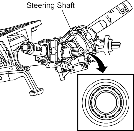
Fig.
1 Steering shaft centering mark at 6 o'clock position. Type 1 & 3
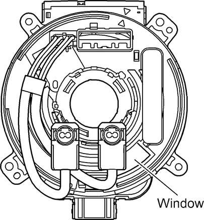
Fig.
2 Clockspring center position. Type 1
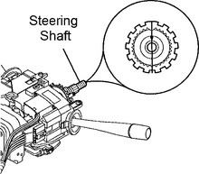
Fig.
3 Steering shaft block tooth at 12 o'clock position. Type 2 & 4
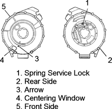
Fig.
4 Clockspring centering. Type 2 w/center window & spring service lock
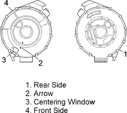
Fig.
5 Clockspring centering. Type 2 w/center window
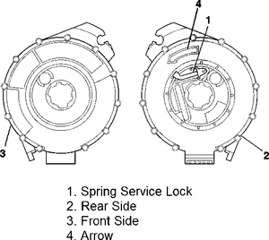
Fig.
6 Clockspring centering. Type 2 w/spring service lock
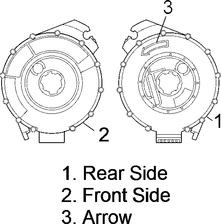
Fig.
7 Clockspring centering. Type 2 less centering window & spring service lock
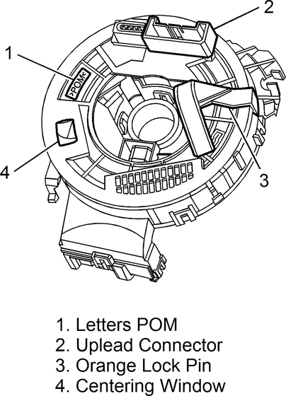
Fig.
8 Centering clockspring. Type 4
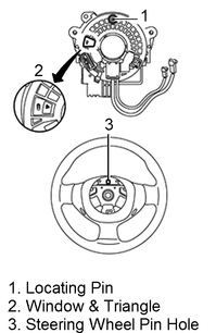
Fig.
9 Centering clockspring. Type 5
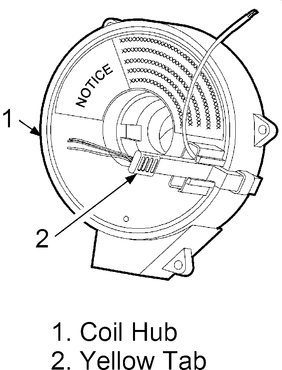
Fig.
10 Centering clockspring. Type 6
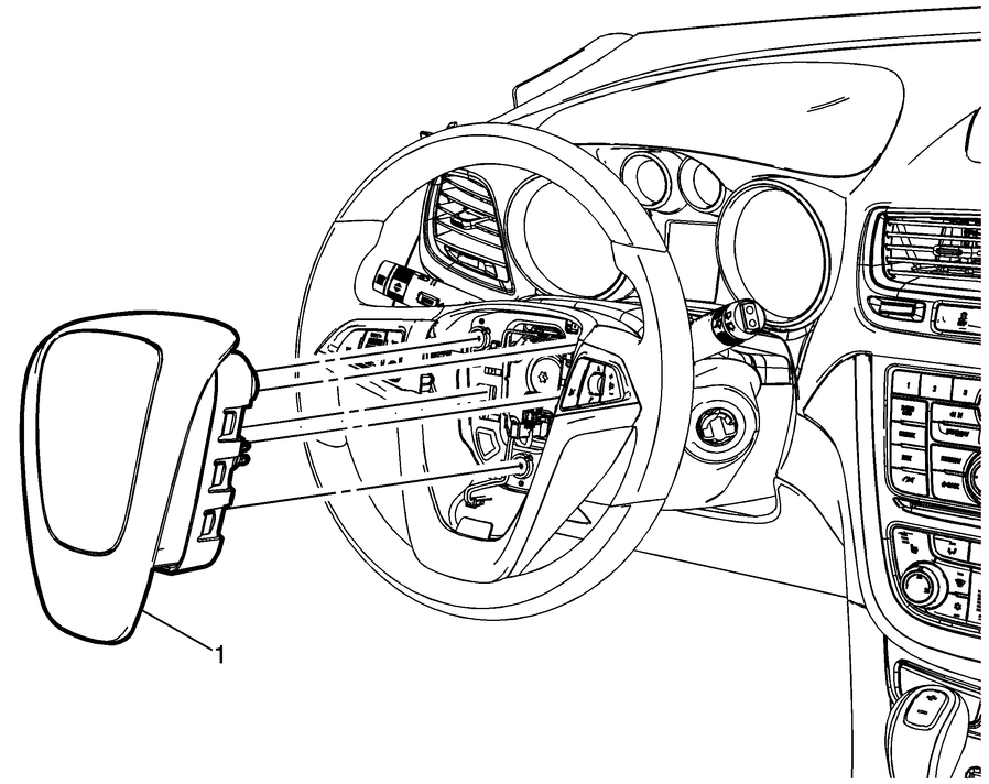
Fig.
11 Driver air bag module removal
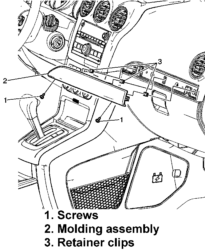
Fig.
12 Instrument panel molding replacement. Captiva Sport
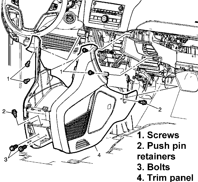
Fig.
13 Front floor console extension panel replacement. Captiva Sport
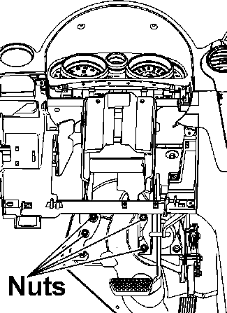
Fig.
14 Instrument panel tie bar to mod plate nuts replacement. Captiva Sport
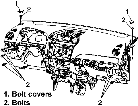
Fig.
15 Instrument panel replacement. Captiva Sport
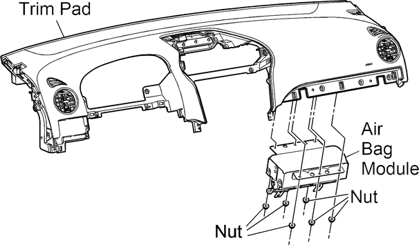
Fig.
16 Passenger air bag module replacement. Captiva Sport
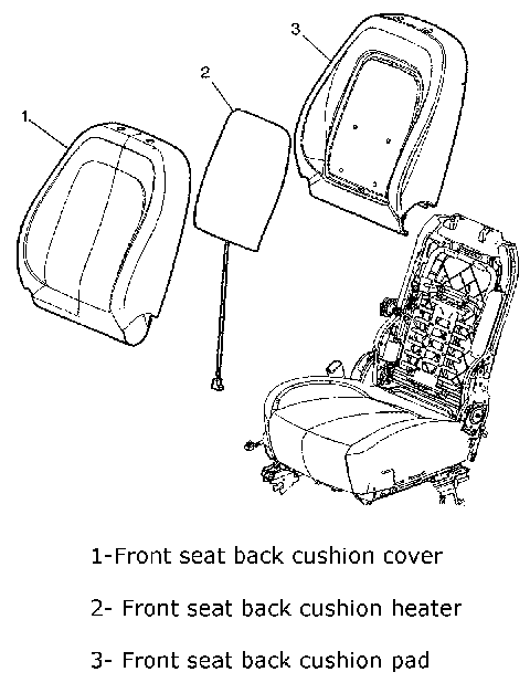
Fig.
17 Seat assembly. Captiva Sport
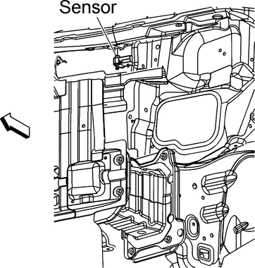
Fig.
18 Front impact sensor replacement. Captiva Sport
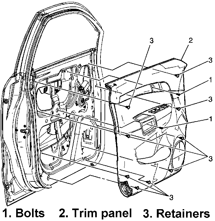
Fig.
19 Front door trim panel replacement. Captiva Sport
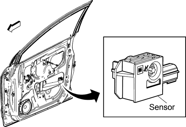
Fig.
20 Front side impact sensor replacement. Captiva Sport
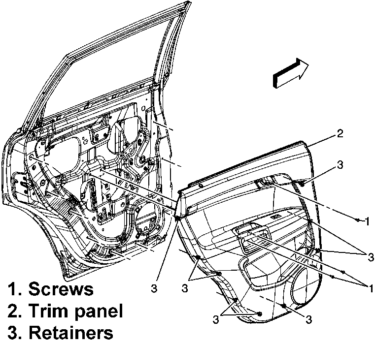
Fig.
21 Rear door trim panel replacement. Captiva Sport
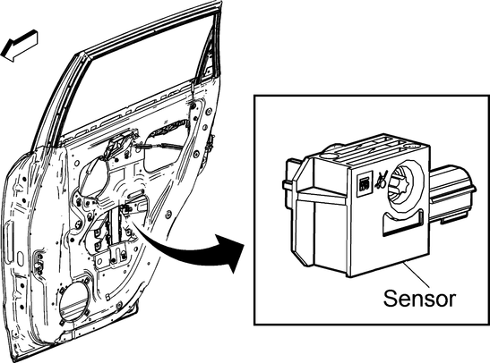
Fig.
22 Rear side impact sensor replacement. Captiva Sport
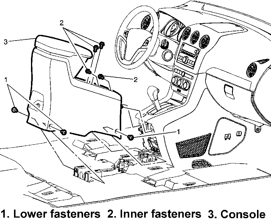
Fig.
23 Floor console replacement. Captiva Sport
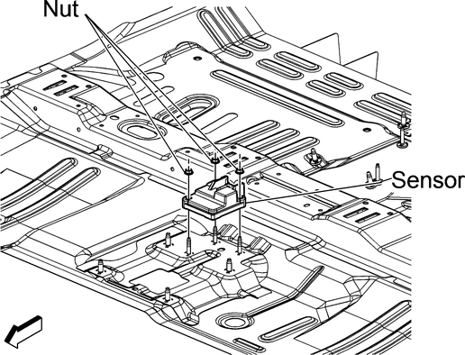
Fig.
24 Rollover sensor replacement. Captiva Sport
Chevrolet Captiva Sport Service and Repair Manual covers a wide range of component services aimed at maintaining and repairing various parts of the vehicle. This manual is a comprehensive guide that technicians and DIY enthusiasts use to perform routine maintenance, diagnose issues, and conduct repairs effectively.
One of the key aspects covered in the manual is the service of engine components. This includes tasks such as inspecting and replacing engine oil, filters, spark plugs, belts, hoses, and other vital engine parts. Proper engine maintenance ensures optimal performance, fuel efficiency, and longevity of the vehicle.
The manual also delves into servicing the vehicle's transmission system. It provides detailed instructions on checking transmission fluid levels, performing fluid changes, and diagnosing transmission-related problems. Proper transmission service is crucial for smooth gear shifts, enhanced driving experience, and preventing costly transmission repairs.
Additionally, the articleincludes guidance on servicing the vehicle's braking system. This involves inspecting and replacing brake pads, rotors, calipers, brake fluid, and other brake components. A well-maintained braking system is essential for vehicle safety, responsive braking performance, and preventing brake-related issues.
Chevrolet Captiva Repair Manual offers comprehensive guidance on servicing and repairing various vehicle components, ensuring optimal performance, reliability, and longevity of the vehicle. It serves as a valuable resource for maintaining and troubleshooting different systems and components of the Chevrolet Captiva.
Refer to Fig. 1
for air bag component locations.
Fig.
1 Component locations. Captiva Sport ...
Year
Component
Torque, Ft. Lbs.
CAPTIVA SPORT
2012-15
Air Bag Control Module
89 1
...
More about:
Chevrolet Captiva Owners Manual > Service and Maintenance: General Information
Your vehicle is an important investment. This section describes the required maintenance for the vehicle. Follow this schedule to help protect against major repair expenses resulting from neglect or inadequate maintenance. It may also help to maintain the value of the vehicle if it is sold. It is ...


 Component Locations
 Tightening Specifications