Chevrolet Captiva Service & Repair Manual: ABS Hydraulic Control Unit R&R
| Caution: Always connect or
disconnect the wiring harness connector from the EBCM/EBTCM with the ignition
switch in the OFF position. Failure to observe this precaution could result
in damage to the EBCM/EBTCM. |
Removal
| 1. |
Turn the ignition switch to the OFF
position. |
| 2. |
Remove the underhood electrical center. |
| 3. |
Without draining the coolant or removing
the hoses, remove and position aside the radiator surge tank. |
| 4. |
Disconnect the electronic brake control
module (EBCM) electrical connector by lifting the locking tabs. |
| 5. |
Disconnect the left front brake pipe
fitting (1) at the brake pressure modulator valve (BPMV), Fig.
1. |
| 6. |
Cap the brake pipe fitting and plug
the BPMV outlet port to prevent brake fluid loss and contamination. |
| 7. |
Disconnect the right front brake pipe
fitting (2) from the BPMV, Fig. 1. |
| 8. |
Cap the brake pipe fitting and plug
the BPMV outlet port to prevent brake fluid loss and contamination. |
| 9. |
Disconnect the master cylinder primary
brake pipe fitting (1) from the BPMV, Fig. 2. |
| 10. |
Cap the brake pipe fitting and plug
the BPMV inlet port to prevent brake fluid loss and contamination. |
| 11. |
Disconnect the master cylinder secondary
brake pipe fitting (2) from the BPMV, Fig. 2. |
| 12. |
Cap the brake pipe fitting and plug
the BPMV inlet port to prevent brake fluid loss and contamination. |
| 13. |
Disconnect the left rear brake pipe
fitting (1) from the BPMV, Fig. 3. |
| 14. |
Cap the brake pipe fitting and plug
the BPMV outlet port to prevent brake fluid loss and contamination. |
| 15. |
Disconnect the right rear brake pipe
fitting (2) from the BPMV, Fig. 3. |
| 16. |
Cap the brake pipe fitting and plug
the BPMV outlet port to prevent brake fluid loss and contamination. |
| 17. |
Remove the BPMV bolt (1), Fig.
4. |
| 18. |
Carefully remove the BPMV assembly
(1) by pulling straight upward, Fig. 5. |
| 19. |
Do not pry on the accumulator caps
on the underside of the BPMV. |
| 20. |
Inspect the insulators for damage and
replace, if necessary. |
|
Installation
| 1. |
Install the BPMV assembly to the bracket. |
| 2. |
Install the BPMV bolt and torque
to 89 inch lbs. |
| 3. |
Connect the left rear brake pipe fitting
to the BPMV and torque to 16 ft. lbs. |
| 4. |
Connect the right rear brake pipe fitting
to the BPMV and torque to 16 ft. lbs. |
| 5. |
Connect the master cylinder primary
brake pipe fitting to the BPMV and torque to 16 ft. lbs. |
| 6. |
Connect the master cylinder secondary
brake pipe fitting to the BPMV and torque to 16 ft. lbs. |
| 7. |
Connect the left front brake pipe fitting
to the BPMV and torque to 16 ft. lbs. |
| 8. |
Connect the right front brake pipe
fitting to the BPMV and torque to 16 ft. lbs. |
| 9. |
Connect the EBCM electrical connector. |
| 10. |
Install the radiator surge tank. |
| 11. |
Install the underhood electrical center. |
| 12. |
Bleed the hydraulic brake system. |
| 13. |
Turn the ignition switch to the ON
position. |
| 14. |
Perform the diagnostic system check. |
| 15. |
Observe the brake pedal feel after
performing the diagnostic system check. If the pedal now feels spongy,
air may have been in, or may have been introduced into the primary
circuit. |
| 16. |
If the pedal feels spongy, perform
the antilock brake system automated bleed. |
|
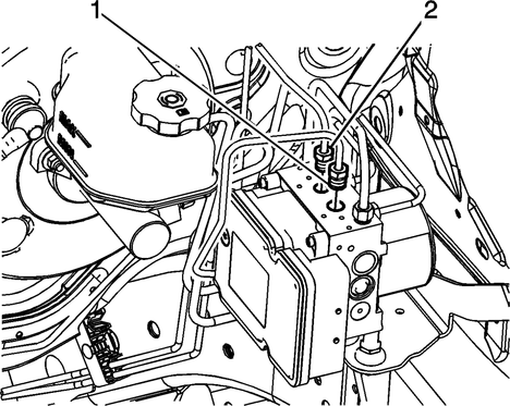
Fig.
1
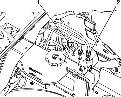
Fig.
2
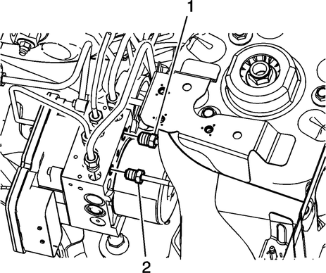
Fig.
3
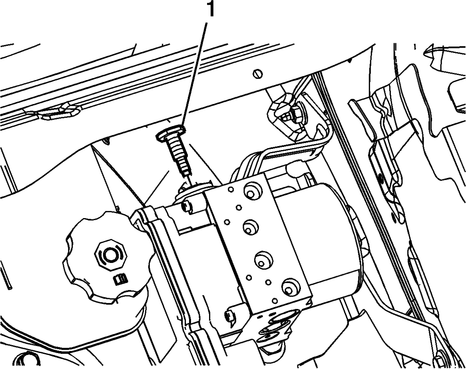
Fig.
4
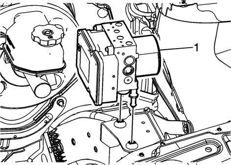
Fig.
5
Replacing the ABS Hydraulic Control Unit (HCU) in a Chevrolet Captiva is a complex but necessary task to ensure the proper functioning of the Antilock Brake System (ABS). The HCU plays a crucial role in regulating brake pressure and preventing wheel lock-up during braking, enhancing vehicle control and safety.
Before starting the replacement process, it's important to disconnect the battery and relieve any residual pressure in the brake system. Locate the ABS HCU, which is typically mounted near the brake master cylinder and brake lines.
Begin by disconnecting the brake lines and electrical connectors from the HCU. Carefully remove any mounting bolts or brackets securing the HCU in place. Take note of the HCU's orientation and position to ensure correct installation of the new unit.
Install the new ABS HCU by aligning it correctly with the brake lines and electrical connectors. Secure the HCU with the mounting bolts or brackets and reconnect the brake lines and electrical connectors.
Once the new HCU is installed, it's crucial to bleed the brake system to remove any air bubbles and ensure proper brake operation. Use a suitable brake fluid and follow the manufacturer's guidelines for bleeding procedures.
After completing the replacement and bleeding process, perform a thorough test of the ABS system to verify its functionality and ensure there are no warning lights or error codes present. Properly replacing the ABS Hydraulic Control Unit in the Chevrolet Captiva helps maintain optimal braking performance and vehicle safety.
Caution: Always connect or disconnect the wiring harness connector from the EBCM/EBTCM with the ignition switch in the OFF position. Failure to observe this precaut ...
Caution: Pull relay straight
out from electrical center terminals, using relay removal tool No. EL-43244,
or equivalent. Use of pliers or a flat bladed tool could damage electrical
...
 ABS Control Module R&R
 ABS Relay R&R