Chevrolet Captiva Service & Repair Manual: Suspension Strut Cartridge R&R
Chevrolet Captiva Service & Repair Manual / Steering & Suspension / Suspension Strut Cartridge R&R
Front
Disassembly
| Caution: Do not allow absorber rod to rotate during disassembly/assembly. Use hand tools to keep absorber rod from rotating. If air tools are used, and rod is allowed to rotate, damage to absorber may occur. |
| Caution: Do not handle top mount assembly by plastic portion. Handle top mount assembly by metal portion when removing/installing top mount from/to strut assembly. Holding top mount assembly by plastic portion may loosen snap fit of bearing components and cause bearing to fall apart. |
| Before removing any of front strut assembly components, note alignment and orientation of all components to aid in installation. |
| Ensure front suspension strut assembly is vertical in spring compressor. |
| Use proper size socket to hold front suspension strut shaft while loosening front suspension strut shaft nut. |
| If any of front suspension strut assembly components show signs of excessive wear or are damaged, replace those components. |
| If front spring does not have to be serviced, leave spring in spring compressor. |
|
Assembly
| Caution: Do not handle top mount assembly by plastic portion. Handle top mount assembly by metal portion when removing/installing top mount from/to strut assembly. Holding top mount assembly by plastic portion may loosen snap fit of bearing components and cause bearing to fall apart. |
| Caution: Do not allow absorber rod to rotate during disassembly/assembly. Use hand tools to keep absorber rod from rotating. If air tools are used, and rod is allowed to rotate, damage to absorber may occur. |
| Ensure that front suspension strut assembly is vertical in spring compressor. |
|
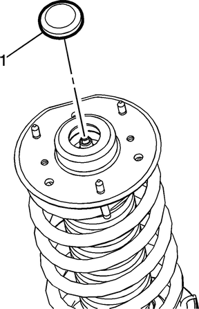
Fig. 1
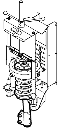
Fig. 2
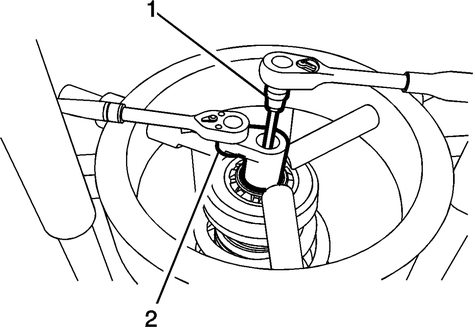
Fig. 3
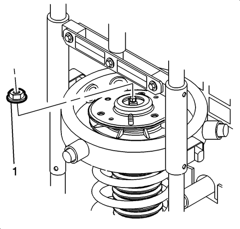
Fig. 4
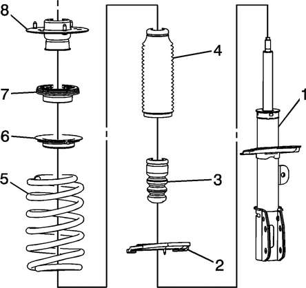
Fig. 5
 Suspension Strut Bearing Assembly R&R
Front
Disassembly
Caution: Do not allow absorber
rod to rotate during disassembly/assembly. Use hand tools to keep absorber
rod from rotating. If air tools are used, and rod is allowe ...
 Suspension Strut Mount Assembly R&R
Front
Disassembly
Caution: Do not allow absorber
rod to rotate during disassembly/assembly. Use hand tools to keep absorber
rod from rotating. If air tools are used, and rod is allowe ...
More about:
Chevrolet Captiva Service & Repair Manual > Serpentine Belt: Drive Belt R&R
1.
Remove air cleaner assembly.
2.
Remove righthand engine splash shield.
3.
Rotate drive belt tensioner, using
a suitable tool, Fig. 1.
4.
Remove drive belt from pulleys and
...
Chevrolet Captiva Owners Manual
- Introduction
- In Brief
- Keys, Doors, and Windows
- Seats and Restraints
- Storage
- Instruments and Controls
- Lighting
- Infotainment System
- Climate Controls
- Driving and Operating
- Vehicle Care
- Service and Maintenance
- Technical Data
- OnStar
Chevrolet Captiva Service & Repair Manual
© 2026 Copyright www.ccaptiva.com - 0.0092
