Chevrolet Captiva Service & Repair Manual: Component Replacement
Tire Pressure Indicator Sensor Replacement
| Use the correct fastener in the
correct location. Replacement fasteners must be the correct part number
for that application. Do not use paints, lubricants, or corrosion inhibitors
on fasteners, or fastener joint surfaces, unless specified. These coatings
affect fastener torque and joint clamping force and may damage the fastener.
Use the correct tightening sequence and specifications when installing fasteners
in order to avoid damage to parts and systems. When using fasteners that
are threaded directly into plastic, use extreme care not to strip the mating
plastic part(s). Use hand tools only, and do not use any kind of impact
or power tools. Fastener should be hand tightened, fully seated, and not
stripped. |
| 1. |
Remove tire and wheel. |
| 2. |
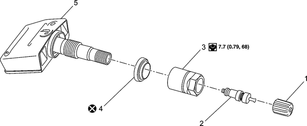
Remove valve stem cap (1), valve
core (2), Valve nut (3) and grommet seal (4), Fig. 1. |
| 3. |
Remove tire pressure indicator sensor (5),
Fig. 1. |
| 4. |
Reverse procedure to install, noting
the following: |
| |
a. |
Torque tire pressure indicator
sensor nut to 40 inch lbs. |
| |
b. |
Perform tire pressure indicator sensor
relearn procedure. |
|
Low Tire Pressure Indicator Module Replacement
| Use the correct fastener in the
correct location. Replacement fasteners must be the correct part number
for that application. Do not use paints, lubricants, or corrosion inhibitors
on fasteners, or fastener joint surfaces, unless specified. These coatings
affect fastener torque and joint clamping force and may damage the fastener.
Use the correct tightening sequence and specifications when installing fasteners
in order to avoid damage to parts and systems. When using fasteners that
are threaded directly into plastic, use extreme care not to strip the mating
plastic part(s). Use hand tools only, and do not use any kind of impact
or power tools. Fastener should be hand tightened, fully seated, and not
stripped. |
| 1. |
Remove instrument panel storage compartment. |
| 2. |
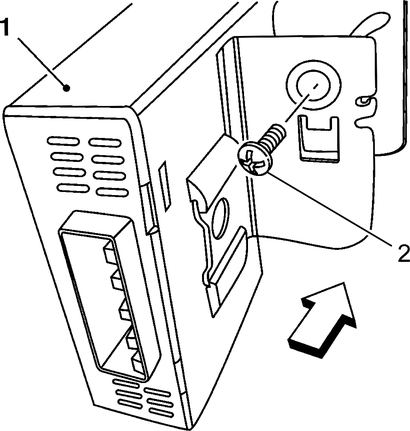
Disconnect electrical wiring harness
connector from low tire pressure indicator module (1), Fig.
2. |
| 3. |
Remove low tire pressure indicator
module fastener (2) and remove module, Fig. 2. |
| 4. |
Reverse procedure to install. |
| 5. |
Perform tire pressure indicator sensor
relearn procedure. |
|

Fig.
1 Tire pressure indicator sensor replacement

Fig.
2 Tire pressure indicator module replacement
Refer to Fig. 1 for component locations.
Fig. 1 TPMS sensor location ...
The TPMS (Tire Pressure Monitor
System) warns the driver when a significant loss or gain of tire pressure
occurs in any of the four tires and allows the driver to display the individual ...
More about:
Chevrolet Captiva Service & Repair Manual > Tires: Diagnosis & Testing
Accessing Diagnostic Trouble Codes
Connect a suitably programmed
scan tool to Data Link Connector (DLC) and follow manufacturers instructions.
Diagnostic Tests
Low tire pressure in one or more
tires is indicated by a continuously illuminated TPMS indicator after the
...


 TPMS sensor location
 Description